Tags & Description
1st Principle of Ultrasound
Ultrasound is a dpeth-based modality that uses the time of flight to determine depth of the anatomy being imaged
2nd Principle of Ultrasound
Ultrasound images come from reflections on medium boundaries, with high reflectivity surfaces having higher intensity reflections
Use of acoustic coupling gel in ultrasound
necessary to prevent air pockets between ultrasound transducer and skin so there are no high impedance boundaries (allows direct contact with the skin)
Attenuation
loss in ultrasound intensity as it travels through a medium, either through acoustic scattering or through attenuation
3rd Principle of Ultrasound
Greater imaging depth and higher frequency results in greater attenuation of the signal
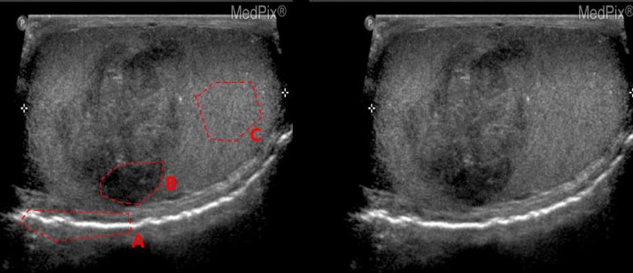
State the ultrasound phenomena in the indicated area (specular reflection, transmission, scattering, enhancement, shadowing)
A: Specular Reflection
B: Transmission
C: Scattering
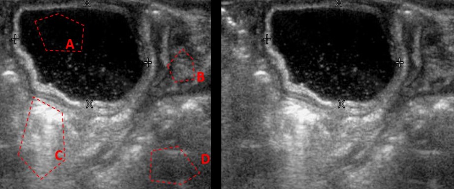
State the ultrasound phenomena in the indicated area (specular reflection, transmission, scattering, enhancement, shadowing)
A: Transmission
B: Scattering
C: Enhancement
D: Scattering (NOT SHADOWING)
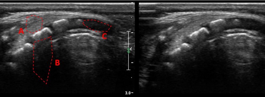
State the ultrasound phenomena in the indicated area (specular reflection, transmission, scattering, enhancement, shadowing)
A: Scattering
B: Shadowing
C: Transmission
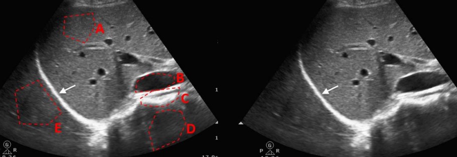
State the ultrasound phenomena in the indicated area (specular reflection, transmission, scattering, enhancement, shadowing)
A: Scattering
B: Transmission
C: Specular Reflection
D: Shadowing
E: Shadowing
Ultrasound transducer thickness formula
thickness = wavelength/2 = 4000/(2*f)
Purpose of Damping Block in Ultrasound
Placed behind transducer to absorb ultrasound
Used to limit the signal’s spatial pulse length (SPL)
Spatial Pulse Length (SPL)
duration of emitted ultrasound signal
Axial resolution formula
Resolution in the direction of the beam
= SPL/2
Purpose of matching layer in Ultrasound
minimizes difference in acoustic impedance between transducer and skin/tissue
optimal thickness is 1/4 wavelength
Lateral resolution formula
Resolution perpendicular to beam direction
= (transducer diameter)/2 in the far-field
4 Components of ultrasound DAQ
Beam former
pulser: provides voltage to piezoelectric element
transmit/receive switch
receiver
Pulse-Echo Operation
Basic mode of ultrasound with an initial pulse followed by a listening ‘echo’ phase
Each pulse sequence produces one A-line of data
Pulse repetition frequency (PRF)
Number of times transducer is pulsed per second
inverse of PRP
Pulse repetition period (PRP)
inverse of PRF
Duty cycle definition
fraction of time for which the ultrasound pulse is “on”
3 display modes of ultrasound
A-mode: displays 2D line plot of amplitude vs. distance
B-mode: displays 1D brightness vs. distance
M-mode: 2D plot of B-mode over time, typically used for moving organs
Dynamic Receive Focusing
change the time delay for received signals depending on imaging depth
Transmit Focusing
Outside transducers fire before the inside transducers for a central focus point
Types of 2D transducer arrays
Linear arrays: subset of elements fire at a time, produces a single A-line and shifts laterally
Phased arrays: elements activated at different times to steer the beam left/right
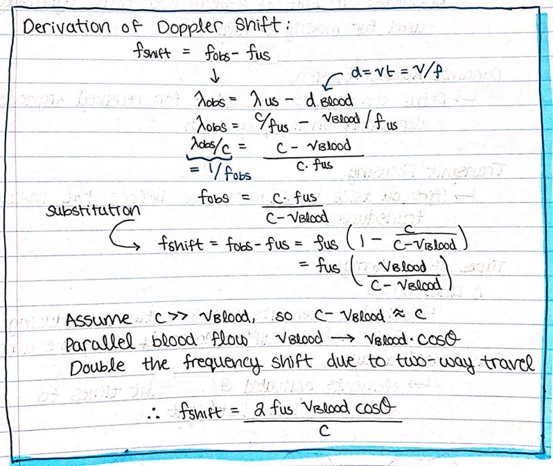
Derivation of Doppler Shift formula
Preferred doppler angle
30-60 degrees
Continuous doppler ultrasound
2 transducers used with one to transmit continuously and another for detection
Pulsed doppler ultrasound
A single transducer in pulse-echo format but with longer SPL
phase change between pulses measured is used to estimate doppler shift
Duplex scanning
combine 2D B-mode imaging with pulsed Doppler to measure flow rates
Color-Flow Imaging
2D visual display of moving blood superimposed on the image
Red flows toward transducer
Blue flows away from transducer
Spectral Doppler Interpretation
spectrum of frequencies received by the Doppler ultrasound which may represent laminar or turbulent flow
Velocity based artifacts
speed propagation
refraction
Reflection based artifacts
reverberation
comet tail
ring down
Multipath reflection
side-lobes
ambiguity
Attenuation based artifacts
shadowing
enhancement
methods of image enhancement
spatial compounding
ultrasound obtained from multiple angles to produce image
Ultrasound contrast agents
microbubble contrast
Harmonic imaging
tune in receive to include harmonic frequencies
Acoustic power (ultrasound power) SPTA & SPPA
spatial peak-temporal average intensity (SPTA)
indicates thermal ultrasound effects
spatial peak-pulse average intensity (SPPA)
indicates bioeffects and cavitation risk
Thermal index
Ratio of acoustical power to raise tissue temperature by 1 degree Celsius
Mechanical index
estimates the likelihood of rarefractions resulting in bubble formation